Types of Interfaces
1.
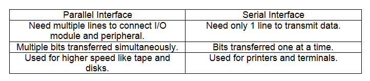
Figure 2.1.1 Parallel Interface and Serial Interface
2. In other case, I/O module is engaged in a dialogue with the peripheral. The dialogue for a write operation is:
- The I/O module request permission to send data by sending a control signal.
- The request is acknowledged by the peripheral.
- I/O module transfers data.
- The receipt of the data is acknowledged by the peripheral.
3. The operation of an I/O module is of an internal buffer that can store data which is passed between the peripheral and the rest of the system. This buffer allows the I/O module to compensate for the differences in speed between the system bus and its external lines.
Point-to-point and Multipoint Configurations
- Point-to-point and multipoint interfaces are connection between an I/O module in a computer system and external devices.
- Point-to-point interface provides a connection between the I/O module and the external device.
- Point-to-point links to keyboard, printer and external modem.
- Example is the EIA-232 specification.
- Multipoint is used to support external mass storage devices and multimedia devices.
- Multipoint interfaces are actually external buses, exhibiting the same type of logic.
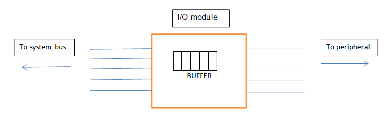
Figure 2.1.2 Parallel I/O
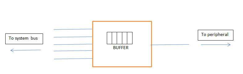
Figure 2.1.3 Serial I/O
Example: InfiniBand
InfiniBand
- Is a recent I/O specification aimed at the high-end server market.
- Was released in 2011.
- For storage area networking, other large storage configuration and attachment of servers, remote storage and other network devices in central fabric of switches and links.
- Can connect up to 64,000 servers, storage systems and networking devices.
InfiniBand Architecture
- The InfiniBand architecture specification defines a connection between processor nodes and high performance I/O nodes such as storage devices.
- Remote storage, other network devices ,and connections between servers are done by joining to the central fabric of switches and links.
- Transmission rates is around 30 Gbps.
- It’s channel design enables I/O devices to be placed at a distance which is:
- about 17 meters away from server using copper.
- about 300m using multi-mode optical fiber.
- about 10km with single-mode optical fiber.
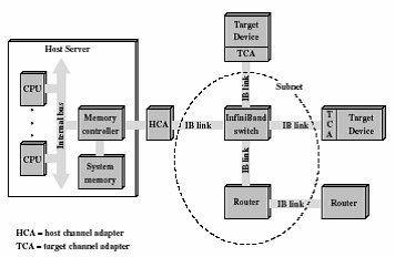
Figure 2.1.4 InfiniBand Switch Fabric
- Host channel adapter (HCA):
- Join to server at a memory controller which can access to the system bus and controls traffic between processor and memory and between the HCA and memory.
- Consists of direct-memory access (DMA)to read and write memory.
- Target channel adapter (TCA):
- For connecting storage system, routers, and other peripheral devices to an InfiniBand switch.
- InfiniBand switch:
- Provides point-to-point physical connections to a variety of devices and switches traffic from one link to another.
- Can help communicate servers and devices through their adapters.
- Manages linkage without interrupting to servers’ operation.
- Links:
- Connects a switch and a channel adapter, or between 2 switches.
- Sub-net:
- Consists of 1 or more interconnected switches with the links between other connections and switches. (Figure above shows sub-net with a single switch.)
- More complex sub-net are required for larger number of devices that are needed to be interconnected.
- Allow administrators to confine broadcast and multicast transmissions within sub-net.
- Router:
- Links sub-net or connects switch to a network, such as local area network(LAN), wide area network(WAN), and storage area network.
Channel adapters can deal with all functions without the involvement of the server’s processor.
InfiniBand switch temporarily opens up communicating channels between processors and devices. Devices do not need to share a channel’s capacity as there is a well-designed bus-based such as PCI that can help the devices to access to the processor. Other additional devices are added to the configuration by hooking to each device’s TCA to the switch.
InfiniBand Operation
16 logical channels, called the virtual lanes can be supported by each link between a switch and an attached interface (HCA or TCA).
All lanes are reserved for data transport except one, which is for fabric management.
Data are sent in the form of a stream of packets, containing some portion of the total data to be transferred, addressing and control information.
The transfer of data is managed by a set of communications protocols.
The transfer of data from 1 end node to another over the InfiniBand fabric is temporarily dedicated by a virtual lane.
The InfiniBand switch maps traffic to an outgoing lane from an incoming lane to route the data between the desired end points.
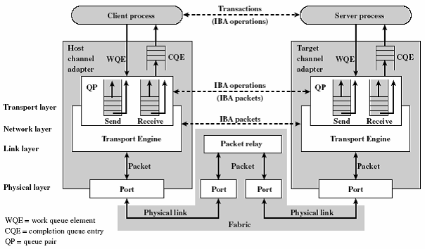
Figure 2.1.5 InfiniBand Communication Protocol Stack
1. The above diagram shows a logical structure used to support exchanges over InfiniBand.
2. Some devices can send data faster than another destination device can receive it, a pair of queues at both ends of each link temporarily buffers excess outbound and inbound data.
3. Queues can be placed in the channel adapter or in a device’s memory.
4. Separate pair of queues is used for each virtual lane.
5. Queues are used in the following method:
- A transaction, called a work queue entry (WQE) is placed by a user into a SEND or RECEIVE queue of the queue pair.
- For a SEND operation, a block of data is specified by the WQE in the device’s memory space for the hardware to send to its destination.
- For a RECEIVE operation, when a user executes a SEND operation, the destination where the hardware is to locate data received from another device is specified by the WQE.
- The channel adapter processes each posted WQE in the proper prioritized order, generating a success queue entry (CQE) to show a completion status.
6. It consists of 4 layers:
- Physical—Defines 3 type of link speeds (1X, 4X, and 12X), which gives transmission rates of 2.5, 10, and 30 Gbps respectively. Refer table below.
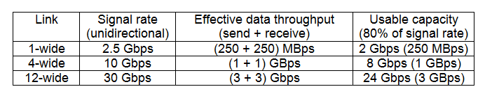
Figure 2.1.6 Table of 3 type of link speeds
- Link—Defines the basic packet structure used to exchange data, addressing scheme that assigns a special link address to every device in a sub-net. This level also includes the logic for setting up virtual lanes and for switching data through switches to destination within a sub-net from source.
- Network—Routes packets between different InfiniBand sub-nets.
- Transport—Provides reliability mechanism for end-to-end transfer of packets across one or more sub-nets.
by Fong
_______________________________________________________________________________________________
Input: Accept or receive or key in.
Output: Produce.
Device: Machine or instrument.
Input and output device: A machine (computer) has many companions such as mouse,keyboard help computer to accept what human want to spread and has many friends like printer and monitor to help human can get and see documents they want.
Examples of Input Devices
Mouse
Optical mouse - It uses a light-emitting diode and photo diodes to detect movement.

Figure 2.2.1 Optical mouse

Figure 2.2.2 Magic mouse
Arc-touch-mouse - wireless and ergonomic.

Figure 2.2.3 Arc-touch-mouse
- Moving the mouse turns the ball.
- X and Y rollers grip the ball and transfer movement
- Optical encoding disks include light holes.
- Infrared LEDs shine through the disks.
- Sensors gather light pulses to convert to X and Y vectors.
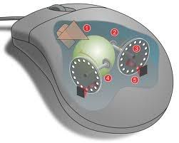
Figure 2.2.4 Mouse Structure
The first computer mouse, held by inventor Douglas Engelbart, showing the big wheels that make contact with the surface.The wheel looks heavier than the mouse we use now.
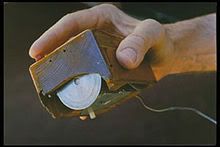
Figure 2.2.5 First computer mouse by Douglas Engelbart
Keyboard
Type text or word by pressing buttons or keys.

Figure 2.2.6 Keyboard

Figure 2.2.7 Fold-able keyboard

Figure 2.2.8 Laptop keyboard
Scanner
Connect to computer system to read bar code of product

Figure 2.2.9 Scanner
CD-Rom Drive
Read info from a CD-ROM
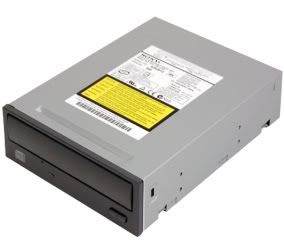
Figure 2.2.10 CD-Rom Drive
- Floppy disk
- Hard disk
- Removable cartridge
Examples of Output Devices
Printer
Produce and print document.

Figure 2.2.11 Printer
Monitor
a screen that can displays files, pictures, text, video.
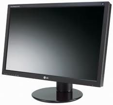
Figure 2.2.12 Monitor
Other Devices
Optical Disk Drive (Input/Output)A disk drive that uses laser light or electromagnetic waves within or near the visible light spectrum as part of the process of reading or writing data to or from optical discs.

Figure 2.2.13 Optical Disk Drive
Magnetic-Tape Unit (Input/Output)
For magnetic recording.

Figure 2.2.14 Magnetic-Tape Unit
Magnetic-Disk Drive Unit (Input/Output)
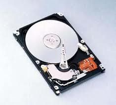
Figure 2.2.15 Magnetic-Disk Drive Unit
_______________________________________________________________________________________________
Module of Input/output
What is I/O Module?
It is the part of a modular PLC (Programmable Logic Controller) to which input and output devices are connected. I/O devices need I/O modules to act as bridge between processor/memory bus and the peripherals.
I/O modules are placed with different functions in modular PLC’s rack. The processor and selection of I/O modules are customized for certain application. A single processor can manage several racks, and have thousands of inputs and outputs. Special high speed serial I/O link is used to have racks distributed away from the processor to reduce the wiring cost.

Figure 2.3.1 Interaction between the I/O module with processor and device interfaces
In the device interface, there will be a control logic acts as the I/O module's interface to the device. Data channel passes the collected data from or to the device through I/O module. A transducer will acts as a converter between the digital data of the I/O module and the signals from environment.
The I/O module’s functions:
Control and timing
o This function enables all multiple devices communicating on the same channel
For example an occurrence happens in CPU, CPU will check the I/O module device status and then I/O module will return the device’s status. CPU requests data transfer when the device is ready. I/O module will get data from device and transfer it to CPU.
Processor communication
o Here shows how the I/O module communicates with the processor and the devices when they involve bus arbitration.
While command decoding, I/O module receives instructions from processor. Example of instructions from processor is READ SECTOR, WRITE SECTOR, SEEK track number, and SCAN record ID.
The data will pass back and forth over the data bus.
Status reporting is the request from the processor for the I/O Module's status to identify whether it is ready or not. Signals are as simple as BUSY and READY.
Address recognition means I/O device is setup as a block of one or more addresses unique to itself.
Device communication
o It is specific to each device. However, communication between device and module is similar to processor communication where they involve instructions, status report and the data.
Data buffering
o Devices usually have slower rate in orders of magnitude but high for main memory and processor. So, due to the differences in speed the I/O module needs to buffer data to keep from tying up the CPU's bus with slow reads or writes.
Error detection
o It just simply distributing the need in watching for errors to the module. Types of errors usually occurs such as malfunctions by device (paper jam), data errors (parity checking at the device level) and internal errors to the I/O module (buffer overruns).

Figure 2.3.2 I/O Module Block Diagram
I/O Module Structure
System bus allows I/O module connects with computer. Collected data from and to the device through I/O module are buffered with data registers. Control registers then send out signals for interaction between module logic and processor. I/O module will receive instructions from processor. Here, address recognition initiated for module to recognize and generate addresses. Control logic will act as the I/O module's interface to the device. I/O module functions make the devices as simple as possible for processor whereas the module may control the device’s details to make it simple.
Reference:
1. Books:Computer Organisation and Architecture-8th Edition by William Stallings
by CSY
_______________________________________________________________________________________________
Principal techniques of Input/output
Programmed I/O
I/O commands:
I/O Instructions
Many I/O devices connect to system through I/O modules. Every device is given a unique identifier or address. When processor distributes an I/O command, commands contain address of desired device. Consequently, I/O module have to interpret address lines to determine if the command is for itself. When I/O, processor, and main memory share a common bus, 2 modes of addressing maybe happened: memory-mapped I/O and isolating I/O.
Interrupt-driven I/O
It overcomes processor having to wait long time for I/O modules. Processor no need check the I/O module status repeatedly.
Device identification (4 general categories of technique):
DIRECT MEMORY ACCESS
Drawbacks of programmed and interrupt-driven I/O.
Interrupt-driven I/O efficient than simple programmed I/O.
DMA function
DMA Operation
I/O commands:
- Control: Activate a peripheral.
- Test: Test various status conditions associated with an I/O module and its peripherals.
- Read: I/O module to obtain an item of data from the peripheral and place it into an internal register.
- Write: I/O module to take a byte or word from data bus and transmit that data item to the peripheral.
I/O Instructions
Many I/O devices connect to system through I/O modules. Every device is given a unique identifier or address. When processor distributes an I/O command, commands contain address of desired device. Consequently, I/O module have to interpret address lines to determine if the command is for itself. When I/O, processor, and main memory share a common bus, 2 modes of addressing maybe happened: memory-mapped I/O and isolating I/O.
- Memory-mapped I/O: only single address space for I/O devices and memory locations. Processor treats status, data registers of I/O modules as memory locations and uses same machine instructions to access I/O devices and memory.
- Isolated I/O: I/O’s address space is isolated from memory.
Interrupt-driven I/O
It overcomes processor having to wait long time for I/O modules. Processor no need check the I/O module status repeatedly.
- I/O module receives a READ command form processor, reads data from desired peripheral into data register, interrupts processors, waits until data is requested by the processor, places data on the data bus when requested.
- Processor issues a READ command, performs some other useful work, checks for interrupts at the end of the instruction cycle, saves current context when interrupted by I/O module, read the data from the I/O module and stores it in memory, restores saved context and resumes execution.
- How does processor determine which device distribute the interrupt?
- Multiple interrupts happened, how does processor decide which one to process?
Device identification (4 general categories of technique):
- Multiple interrupt lines: Each line will have multiple I/O modules attached to it.
- Software poll: A separate command line, Processor reads status register of each I/O module,but software poll is time consuming.
- Daisy chain (hardware poll,vectored): All I/O modules share a common interrupt request line, processor sends out interrupt acknowledge, requesting I/O module places a word of data on data lines (vector), processor uses vector as pointer to appropriate device-service routine this avoid the need to execute general interrupt-service routine first(vectored interrupt).
- Bus arbitration (vectored): 1 module can raise line at a time,processor responds on interrupt acknowledge line, I/O module places its vector of data lines.
DIRECT MEMORY ACCESS
Drawbacks of programmed and interrupt-driven I/O.
Interrupt-driven I/O efficient than simple programmed I/O.
- I/O transfer rate is limited by speed.
- Processor is tied up in managing I/O transfer.
DMA function
- Mimicking processor.
- Taking over control of system from processor.
- DMA module use bus only when processor doesn't need it.
- Cycle stealing: DMA module force processor to suspend operation temporarily.
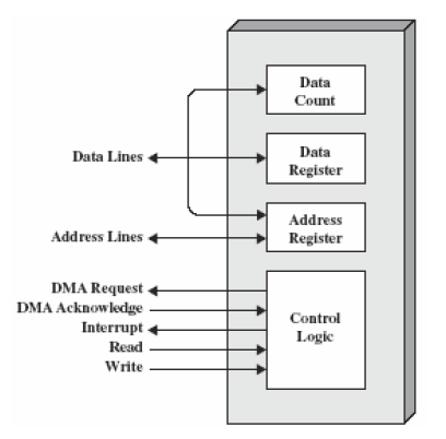
Figure 2.4.1 Typical DMA Block Diagram
DMA Operation
- Processor issues a command to DMA module by sending...
- Read/write control line between processor, DMA module.
- I/O device address.
- Starting memory address using data lines,stored by DMA module in address register.
- Number of words to be read or written transferred using data lines,stored in data count register to DMA module.
- Processor continues with other work.
- DMA module transfers the entire block of data (one word per time) directly to or from memory without going through processor.
- DMA module sends interrupt signal to processor when transfer is complete.
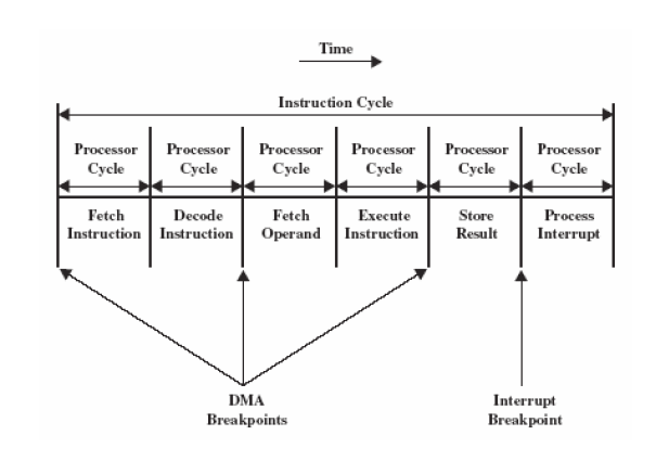
Figure 2.4.2 DMA and interrupt breakpoints during an instruction cycle
Processor suspended before it needs to use bus. DMA module transfer 1 word and returns control to processor. This is not interrupt,processor doesn't save context and do something else. Processor pauses for 1 bus cycle. The effect is to cause processor execute slower. DMA efficient than interrupt-driven or programmed I/O.
3 types of alternative DMA configuration:
1) Single-bus, detached DMA
- Bus cycle: I/O to DMA, DMA to memory (inefficient).
- Processor suspended twice.
2) Single-bus, integrated DMA-I/O
- Module may support more than one device.
- Each transfer uses bus once – DMA to memory
- Processor suspended once.
3) I/O bus
- Bus supports all DMA enabled devices.
- Each transfer uses bus once – DMA to memory
- Processor suspended once.
Reference:
1. Books:Computer Organisation and Architecture-8th Edition by William Stallings
1. Books:Computer Organisation and Architecture-8th Edition by William Stallings
by Wan Bing
_______________________________________________________________________________________________
Input/Output Channels and Processors
Introduction
I/O devices can access and execute application software directly from main memory without any processor intervention.These are I/O channels. Other I/O devices, I/O processors, are computer systems in their own right taking the
functionality of the processor and distributing it to the end devices
The Evolution of the I/O Function
As computer systems have evolved, there has been a pattern of increasing complexity of individual components. The evolutionary steps can be summarized as follows:
As one proceeds along this evolutionary path, more and more the I/O function is performed without processor involvement. The CPU is increasingly relieved of I/O-related tasks, improving performance
Characteristics of I/O Channels
The I/O channel represents an extension of the Direct Memory Access(DMA) concept. An I/O channel has the ability to execute I/O instructions, which gives it complete control over I/O operations.The CPU does not execute I/O instructions itself. Thus, the CPU initiates an I/O transfer by instructing the I/O channel to execute a program in memory. The program will specify the device or devices, the areas of memory, priority and error conditions actions.
There are two common types of I/O channels:
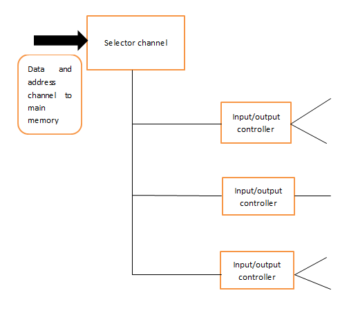
1)Selector channel-A selector channel can controls multiple high-speed devices with different time, is dedicated to one device at a time. Each device is handled by a controller, or I/O module. The I/O channel CPU controlling these I/O controllers.
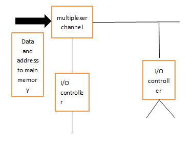
2)Multiplexer channel-A multiplexer channel can operating with a number of I/O devices simultaneously and can used with low speed or high speed of devices. For low-speed devices, a byte multiplexer accepts or transmits characters as fast as possible to multiple devices. For high-speed devices, a block multiplexer interleaves blocks of data from several devices.
Example of the diagram of channel:
a) Selector channel
I/O devices can access and execute application software directly from main memory without any processor intervention.These are I/O channels. Other I/O devices, I/O processors, are computer systems in their own right taking the
functionality of the processor and distributing it to the end devices
The Evolution of the I/O Function
As computer systems have evolved, there has been a pattern of increasing complexity of individual components. The evolutionary steps can be summarized as follows:
- CPU directly controls device.
- Addition of a controller or I/O module. The CPU uses programmed I/O without interrupts.
- Same as step 2 but now interrupts is added so the CPU no need spend time waiting for an I/O operation to be performed thus more efficiency.
- I/O module direct access to memory using DMA.
- I/O module become processor like I/O channel.I/O processor executes program and generates interrupt on completion
- I/O module has local memory and is a computer in its own right. The I/O processor takes care of most of the tasks involved in controlling.
As one proceeds along this evolutionary path, more and more the I/O function is performed without processor involvement. The CPU is increasingly relieved of I/O-related tasks, improving performance
Characteristics of I/O Channels
The I/O channel represents an extension of the Direct Memory Access(DMA) concept. An I/O channel has the ability to execute I/O instructions, which gives it complete control over I/O operations.The CPU does not execute I/O instructions itself. Thus, the CPU initiates an I/O transfer by instructing the I/O channel to execute a program in memory. The program will specify the device or devices, the areas of memory, priority and error conditions actions.
There are two common types of I/O channels:
1)Selector channel-A selector channel can controls multiple high-speed devices with different time, is dedicated to one device at a time. Each device is handled by a controller, or I/O module. The I/O channel CPU controlling these I/O controllers.
2)Multiplexer channel-A multiplexer channel can operating with a number of I/O devices simultaneously and can used with low speed or high speed of devices. For low-speed devices, a byte multiplexer accepts or transmits characters as fast as possible to multiple devices. For high-speed devices, a block multiplexer interleaves blocks of data from several devices.
Example of the diagram of channel:
a) Selector channel
b) Multiplexer channel
by Jian Tung
Really you have done a good job. Thanks for sharing this valuable information....
ReplyDeleteEmbedded System Courses in Chennai
Embedded Course in Coimbatore
Embedded Training in Chennai
Embedded Training in Coimbatore
Embedded Systems Training in Chennai
Embedded Systems Course in Coimbatore
Embedded Systems Training in Chennai
Embedded Training Institute in Coimbatore
ReplyDeleteIt is very useful and knowledgeable. Therefore, I would like to thank you for the efforts you have made in writing this article.
WS-C3650-24PS-E
WS-C3650-24TD-L
WS-C3650-24PD-S